

Capacitor Replacement
 In the element base of the computer (and not only) there is one bottleneck – electrolytic capacitors. They contain electrolyte, electrolyte is a liquid. Therefore, heating such a capacitor leads to its failure, since the electrolyte evaporates. And heating in the system unit is a regular thing.
Therefore, replacing capacitors is a matter of time. More than half of the failures of motherboards of the middle and lower price category are caused by dried or swollen capacitors. Even more often, for this reason, computer power supplies break down.
swollen capacitors
Since the print on modern boards is very dense, you need to very carefully replace the capacitors. It is possible to damage and at the same time not to notice a small open element or tear (shorten) the tracks, the thickness and distance between which is slightly larger than the thickness of a human hair. Correcting this later is quite difficult. So be careful.
So, to replace the capacitors, you need a soldering iron with a thin sting with a power of 25-30W, a piece of a thick guitar string or a thick needle, a soldering flux or rosin.
In the event that you reverse the polarity when replacing an electrolytic capacitor or install a capacitor with a low voltage rating, it may well explode. And here is what it looks like:
exploded capacitor
So carefully select the replacement part and install it correctly. On electrolytic capacitors, a negative contact is always marked (usually a vertical strip of a color different from the color of the case). On the printed circuit board, the hole for the negative contact is also marked (usually with black shading or solid white). The ratings are written on the capacitor housing. There are several of them: voltage, capacitance, tolerances and temperature.
The first two are always there, the rest may be absent. Voltage: 16V (16 volts). Capacity: 220µF (220 microfarads). These values are very important when replacing. The voltage can be selected equal or with a larger rating. But the capacity affects the charging / discharging time of the capacitor and in some cases can be important for the circuit section.
Therefore, the capacity should be selected equal to the one indicated on the case. On the left in the photo below is a green swollen (or leaked) capacitor. In general, there are constant problems with these green capacitors. The most frequent replacement candidates. On the right is a working capacitor, which we will solder.
nominal capacitor selection
The capacitor is soldered as follows: first find the capacitor legs on the back of the board (for me this is the most difficult moment). Then heat one of the legs and lightly press on the condenser body from the side of the heated leg. When the solder melts, the capacitor tilts. Perform the same procedure with the second leg. Usually the capacitor is removed in two steps.
There is no need to rush, too much pressure. Mat.plata is not a double-sided textolite, but multi-layer (imagine a waffle). Excessive diligence can damage the contacts of the internal layers of the printed circuit board. So without fanaticism. By the way, long-term heating can also damage the board, for example, lead to delamination or separation of the contact pad. Therefore, it is also not necessary to press hard with a soldering iron. Lean the soldering iron, slightly press on the capacitor.
Drinking capacitors Drinking capacitors Drinking capacitors
After removing the damaged capacitor, it is necessary to make holes so that the new capacitor is inserted freely or with little effort. For these purposes, I use a guitar string of the same thickness as the legs of the part to be soldered. A sewing needle is also suitable for these purposes, but the needles are now made of ordinary iron, and the strings are made of steel. There is a chance that the needle will seize with solder and break when you try to pull it out. And the string is quite flexible and steel with solder seizes much worse than iron.
preparation of the site for the capacitor
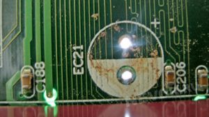
When removing capacitors, solder most often clogs holes in the board. If you try to solder the capacitor in the same way that I advised to solder it, you can damage the contact pad and the track leading to it. Not the end of the world, but a very undesirable occurrence. Therefore, if the holes are not clogged with solder, you just need to expand them. And if you still scored, then you need to firmly press the end of the string or needle to the hole, and on the other side of the board, lean the soldering iron against this hole. If this option is inconvenient, then the soldering iron tip must be leaned against the string almost at the base. When the solder melts, the string enters the hole. At this moment, it is necessary to rotate it so that it does not catch on solder.
After receiving and expanding the hole, excess solder should be removed from its edges, if any, otherwise a tin cap may form during soldering of the capacitor, which can solder adjacent tracks in those places where the seal is tight. Pay attention to the photo below – how close to the holes are the tracks. Soldering this is very easy, but difficult to notice, because the installed capacitor interferes with the review.